LED Tiles “v2” #
| Manufacturer | digiLED |
|---|---|
| Model | P7.8F1MR47S2.1 |
| Size | 500×125 mm |
| Resolution | 64×16 px |
| Colour depth | 1-bit |
| Pixel pitch | 7.8 mm |
| Supply voltage | 5 V |
| Supply current | ~ 8 A |
History #
These tiles were donated to London Hackspace in 2017. A batch of the same tiles was also donated to SYN Shop in Las Vegas at the same time. They originally formed part of the digiLED MC7 LED screen.
The majority of the tiles in the UK now reside at Limehouse Labs, and we’re looking to give these away to make room for newer stuff.
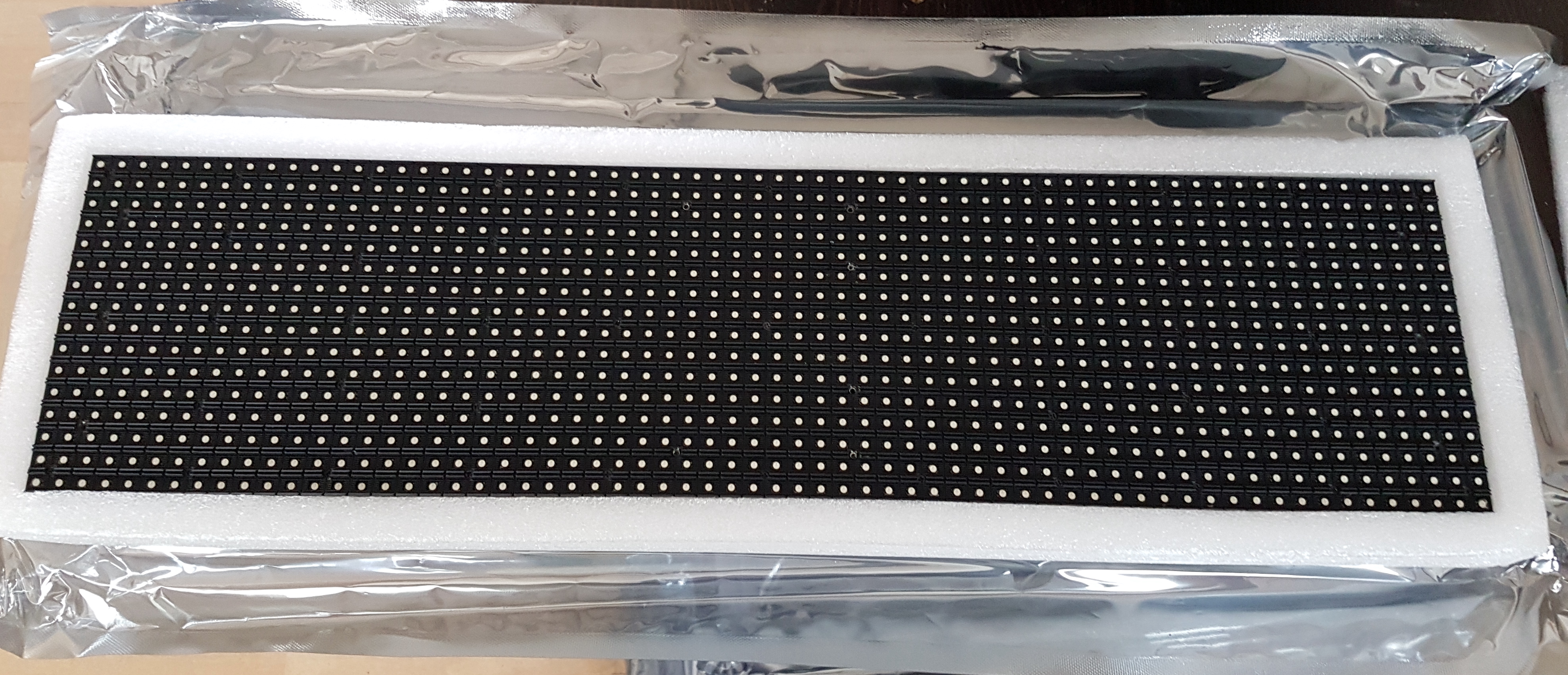
Description #
These tiles have a 1-bit colour depth and so displaying more than 8 colours requires the use of temporal dithering (PWM). This (plus the number of I/O pins) will restrict the number of panels which can be driven from a microcontroller.
There are 48 x Macroblock MBI5034 LED controller chips on the PCB, which are 16-bit shift register constant current sinks.
The controller chips are labelled R,G & B 1-16. So each chip does 16 LEDs of the same colour. They each have a current set resistor. You can also set the current gain in software from 12.5% to 200% but this set the gain for all LEDs attached to that chip, not individual LEDs. The default power gain is 100%.
There are two address line inputs and the LED chips seem to be soldered in to banks of 4. Which makes sense.
There is an HC138 decoder on the address lines, and only the first four outputs seem to be wired. Again, matches the above.
There are also 8 dual FET chips, which seem to control the 4 banks.
Interface #
There are three conventional 2x4 pin 2.54mm header connectors on the board. The top connector is 5V, the middle connector is data, and the bottom is ground.
Note that there is no polarity protection. If you reverse 5V and GND you will fry the board.
| 5V | 5V | 5V | 5V |
| 5V | 5V | 5V | 5V |
| D1 | LAT | A1 | NC |
| D2 | OE | A0 | CLK |
| GND | GND | GND | GND |
| GND | GND | GND | GND |
A0 and A1 are the address lines which select a pair of rows. D0 and D1 are serial data lines which accept interleaved 16-byte BGR data.
A KiCAD project for a simple breakout PCB which supplies power and data to all three connectors is available here.
Using controller cards #
If you want to build a substantial screen out of these tiles, you should consider a commercial controller.
The receiver card originally recommended was the Novastar MRV336 (note: not MRV366), but these cards only output HUB75 which is not the protocol used by these screens.
An appropriate receiver card is probably the MRV420/MRV300 which supports “64-group serial data mode”. This is broken down into groups of channels which have 4 address lines (A, B, C, D), 16/32 data lines, as well as OE, LAT, and CLK outputs.
Russ at Limehouse Labs has tried to get this working but ran into some issues with colour. If you’re interested in trying this approach please get in touch – we have the Novastar gear at Limehouse.
Example code #
- Arduino code for 4 panels from Jon Russell
- Micropython driver
Links #
- London Hackspace wiki page, where some of this info is sourced from
- More photos and datasheets from SYN Shop
- Hitchin Hackspace wiki page and massive gameboy
- Hackspace LED Panels - a good explanation of how to drive the panels with Arduino